




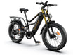
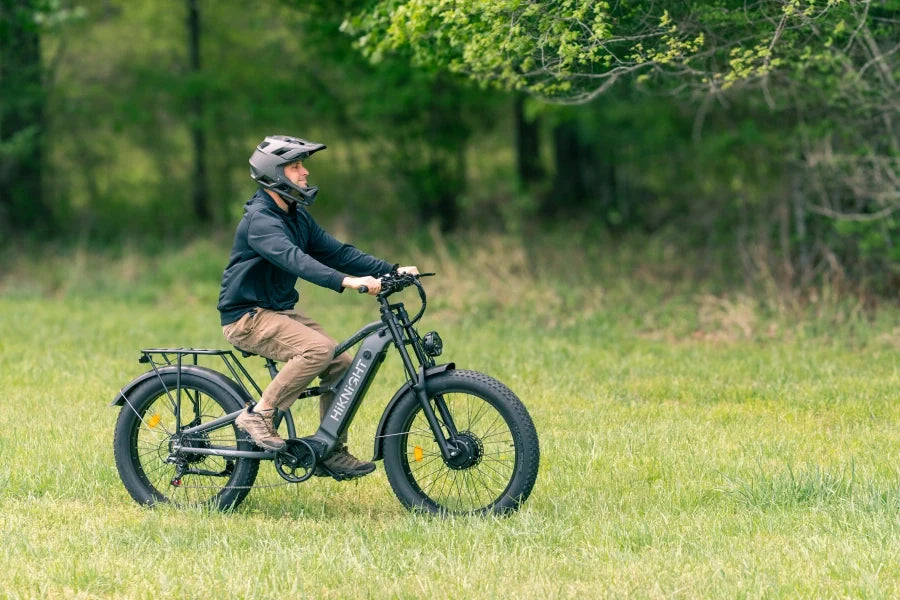
An electric bike equipped with pedal assist operates on a fundamentally different mechanical and biomechanical principle than a throttle-only electric vehicle. Rather than substituting human biomechanics with an electric motor, pedal assist systems (PAS) integrate motor output directly into the rider’s pedaling stroke. This creates a hybrid powertrain where human power and electrical power act in tandem. Whether navigating multi-mile urban commutes, climbing steep gradient fire roads, or managing physiological loads during physical rehabilitation, pedal assist dynamically amplifies rider effort. This comprehensive guide analyzes the mechanical engineering, sensor electronics, energy consumption equations, physiological impacts, and regulatory frameworks governing pedal assist electric bikes.
Table of Contents
- The Mechanical & Electronic Architecture of Pedal Assist Systems
- Biomechanics: Human Power Output vs. Motor Input
- Pedal Assist vs. Throttle-Only: Engineering & Mechanical Comparisons
- Range Physics & Battery Consumption Equations
- Physiological Impact: Clinical Exercise & Biomechanical Data
- Legal Frameworks, Classifications, and Trail Access Protocols
- Optimizing Sensor Types, Motor Configurations, and Gear Ratios
- Practical Maintenance, Diagnostics, and Component Longevity
- Frequently Asked Questions
The Mechanical & Electronic Architecture of Pedal Assist Systems
A Pedal Assist System (PAS)—often referred to as a pedelec—is an automated drive mechanism that activates an electric motor exclusively when mechanical force or rotation is detected at the crank or bottom bracket. The system disengages electrical current to the motor instantly when pedaling ceases or when a preset velocity threshold is reached.
The electronic architecture relies on a closed-loop feedback mechanism consisting of four primary components:
- Rotational or Force Sensors: Located at the bottom bracket, rear dropout, or motor housing to monitor rider input.
- Electronic Controller: A microprocessor that processes sensor frequency or voltage signals, calculating current draw via Pulse-Width Modulation (PWM).
- Lithium-Ion Battery Pack: Provides direct current (DC) electrical energy (typically 36V, 48V, or 52V architectures).
- Brushless DC (BLDC) Motor: Converts electrical energy into mechanical torque, housed either within the wheel hub or integrated into the frame's bottom bracket (mid-drive).

Sensor Dynamics: Cadence vs. Torque Measurement
The operational profile of a pedal assist system is determined by its sensing technology. The industry utilizes two primary sensor variants to measure rider activity:
Cadence Sensors (Speed-Based Sensing)
Cadence sensors utilize a magnetic disc mounted to the crank spindle alongside a stationary Hall-effect sensor. As the rider pedals, the disc rotates past the sensor, generating high and low voltage pulses. The controller calculates rotational frequency (Revolutions Per Minute - RPM). When the pulse frequency exceeds a calibrated threshold, the controller sends a predetermined current to the motor based on the selected PAS level.
- Binary Operation: Current delivery is governed primarily by pedal rotation, irrespective of the physical force applied by the rider.
- Latency Profile: Requires approximately 180° to 360° of crank rotation (half to one full turn) to initiate motor engagement and up to 1 second to disengage upon pedal cessation (mitigated by integrated brake cutoff switches).
- Practical Impact: Provides a consistent, predictable motor boost that requires minimal leg force to sustain momentum once rotation is initiated. This system is widely utilized in heavy-duty utility and commuter platforms such as the HiKNiGHT H2 commuter e-bike.
Torque Sensors (Force-Based Sensing)
Torque sensors utilize strain gauges or optical sensors integrated into the bottom bracket axle, rear dropout, or motor casing. These sensors measure micro-deflections in the metal caused by physical force applied to the pedals, outputting a continuous analog voltage signal proportional to human torque (measured in Newton-meters, N·m).
- Proportional Modulation: Motor assistance scales directly with human effort. If a rider exerts 50 N·m of force, the system scales output proportionally according to the assist multiplier (e.g., 100% in Eco, 300% in Turbo).
- Latency Profile: Ultra-low latency response times (typically under 10 milliseconds), delivering immediate torque from a complete standstill.
- Practical Impact: Eliminates sudden surges in power. The sensation mirrors conventional cycling mechanics with amplified muscular output, making it highly effective for technical off-road maneuvers and steep gradient ascents.
Biomechanics: Human Power Output vs. Motor Input
Understanding the physiological mechanics of pedal assist requires analyzing rider wattage alongside motor power curves. An average non-professional adult cyclist generates between 100 and 150 watts of continuous mechanical power on flat ground, peaking at 250 to 400 watts during short sprint efforts or steep climbs.
| Rider Profile | Sustained Human Power | Motor Contribution (PAS Level 1-2) | Motor Contribution (PAS Level 4-5) | Combined System Output |
|---|---|---|---|---|
| Recreational / Rehab Rider | 50 W – 90 W | 75 W – 150 W | 350 W – 750 W | 125 W – 840 W |
| Average Commuter | 100 W – 150 W | 100 W – 200 W | 500 W – 1000 W | 200 W – 1150 W |
| Trained Cyclist | 200 W – 300 W | 100 W – 150 W | 750 W – 1500 W+ | 300 W – 1800 W+ |
Reducing Patellofemoral & Joint Shear Forces
When climbing steep gradients on a traditional, non-electric bicycle, cadence drops significantly (often below 50 RPM) unless low gearing is maintained. Low cadence under high resistance increases joint reaction forces at the knee joint. Specifically, patellofemoral compressive forces spike rapidly during high-torque, low-RPM pedal strokes, accelerating wear on articular cartilage and straining the patellar tendon.
Pedal assist alters this biomechanical stress curve:
- Cadence Preservation: By supplying instantaneous supplemental torque (e.g., 80 N·m to 160 N·m), the motor absorbs peak mechanical resistance. This allows the rider to maintain an optimal aerobic pedaling cadence between 70 and 90 RPM even on steep inclines.
- Reduction of Peak Torque Spikes: Muscular force spikes during the dead-center phases of the pedal stroke (12 o'clock and 6 o'clock positions) are smoothed out, decreasing shear stress across the anterior cruciate ligament (ACL) and meniscus.
- Controlled Metabolic Load: Riders can keep their physical effort within targeted heart-rate zones, preventing involuntary anaerobic fatigue during climbs.
Pedal Assist vs. Throttle-Only: Engineering & Mechanical Comparisons
While many high-performance fat tire e-bikes feature both throttle and pedal assist functionality, analyzing the electrical and mechanical differences between these two operational modes highlights distinct mechanical consequences.
| Engineering Metric | Pedal Assist Mode (PAS) | Throttle-Only Mode |
|---|---|---|
| Peak Current Draw (Amperes) | Moderate & Gradual (Smoothed by leg power) | High & Instantaneous (Spikes on dead stops) |
| Motor Thermal Accumulation | Low to Moderate (Human power reduces load) | High (Sustained heavy electrical resistance) |
| Battery Energy Efficiency | 10 Wh/mi – 18 Wh/mi | 25 Wh/mi – 45 Wh/mi |
| Mechanical Strain on Gears/Hub | Distributed across human & motor drivetrains | Concentrated entirely on motor planetary gears / hub |
| Legal Classification (US/EU) | Class 1, Class 3 / EPAC (Broad access) | Class 2 / Moped (Restricted on non-motorized paths) |
Electrical Efficiency and Heat Dissipation
When an electric motor operates from a complete standstill using throttle activation alone, the motor experiences its highest current draw (Inrush Current). Because the rotor is turning slowly, back-electromotive force (Back-EMF) is minimal, causing a temporary spike in electrical resistance ($I^2R$ losses). This resistance converts a portion of the electrical energy directly into heat within the motor windings.
In contrast, using pedal assist to initiate motion reduces current spikes dramatically:
- The rider provides the initial kinetic energy required to overcome static inertia.
- The motor engages while already in motion, operating within a higher RPM efficiency band (typically 75% to 85% efficiency).
- Operating at higher motor RPMs minimizes thermal build-up within the controller MOSFETs and stator windings, extending component longevity.
Range Physics & Battery Consumption Equations
To accurately calculate how pedal assist extends operational range, we must evaluate the mathematical relationship between energy storage, vehicle mass, aerodynamic drag, rolling resistance, and human energy input.
Total resistive forces acting on a moving e-bike ($F_{total}$) are represented by:
Ftotal = Frolling + Fdrag + Fgravity
Where:
- Rolling Resistance ($F_{rolling}$): $C_{rr} \cdot m \cdot g \cdot \cos(\theta)$ (where $C_{rr}$ is the tire rolling coefficient, higher on wide 4.0" fat tires).
- Aerodynamic Drag ($F_{drag}$): $\frac{1}{2} \cdot \rho \cdot v^2 \cdot C_d \cdot A$ (where $v$ is velocity relative to air, $C_d$ is drag coefficient, $A$ is frontal surface area).
- Gravitational Resistance ($F_{gravity}$): $m \cdot g \cdot \sin(\theta)$ (where $m$ is combined mass of rider and bike, $\theta$ is gradient angle).
Total power required to maintain a constant speed ($P_{required}$) is:
Prequired = Ftotal · v / ηdrivetrain
In a pedal assist system, $P_{required}$ is supplied by two distinct energy sources:
Prequired = Phuman + Pelectrical
Energy Consumption Analysis Across PAS Levels
Consider a 52V 20Ah battery pack delivering 1,040 Watt-hours (Wh) of total energy capacity installed on an all-terrain e-bike platform such as the HiKNiGHT H2 Pro. The table below illustrates how human wattage contributions directly scale total range over flat to rolling terrain at 20 mph:
| Operational Mode | Human Input (Phuman) | Motor Input (Pelectrical) | Energy Consumption Rate | Calculated Range (1040Wh Battery) |
|---|---|---|---|---|
| Throttle Only (0% Human) | 0 Watts | 350 Watts | 31.5 Wh / mile | ~33 Miles (53 km) |
| PAS Level 5 (Turbo / High) | 50 Watts | 300 Watts | 27.0 Wh / mile | ~38 Miles (61 km) |
| PAS Level 3 (Sport / Medium) | 100 Watts | 250 Watts | 22.5 Wh / mile | ~46 Miles (74 km) |
| PAS Level 2 (Tour / Low) | 125 Watts | 150 Watts | 13.5 Wh / mile | ~77 Miles (124 km) |
| PAS Level 1 (Eco / Min Assist) | 150 Watts | 75 Watts | 9.0 Wh / mile | ~115 Miles (185 km) |
Because aerodynamic drag increases quadratically with speed ($v^2$), human energy contributions are particularly effective at lower and moderate velocities (12–18 mph). At these speeds, a modest 100-watt pedaling input reduces energy draw on the battery by nearly 50%, doubling total range.
Physiological Impact: Clinical Exercise & Biomechanical Data
Contrary to the assumption that electric assist eliminates physical exertion, scientific measurements using metabolic carts, heart rate monitors, and power meters demonstrate that pedal assist e-bikes deliver consistent cardiovascular exercise.

Cardiovascular Intensity Metrics (VO2 & HRmax)
A study published in the International Journal of Behavioral Nutrition and Physical Activity monitored physiological metrics across traditional cyclists and e-bike riders over identical test routes. Key findings included:
- Heart Rate Management: E-bike riders operated at an average of 75% to 85% of their Maximum Heart Rate ($\text{HR}_{\max}$) during pedal assist riding. This falls directly within Zone 2 and Zone 3 aerobic physical training parameters recommended by the American Heart Association for cardiovascular conditioning.
- Oxygen Consumption ($\text{VO}_2$): Mean $\text{VO}_2$ during e-bike usage averaged 51% to 63% of $\text{VO}_2\text{ max}$, which easily satisfies global clinical guidelines for moderate-intensity aerobic physical activity ($>3.0$ METs).
- Perceived Exertion (RPE Scale): On the Borg Rating of Perceived Exertion (6 to 20 scale), traditional cycling on hilly terrain rated at 15–17 ("Hard to Very Hard"), whereas e-bike riding over the same elevation profile rated at 11–12 ("Light to Fairly Light").
Metabolic Equivalent (MET) Breakdown
Cardiovascular and metabolic demand is classified using Metabolic Equivalent of Task (MET) values (1 MET = energy expended sitting at rest):
- Stationary / Driving Motor Vehicle: 1.3 – 1.5 METs
- Walking at 3.0 mph: 3.3 METs
- E-Bike Riding (Low/Medium Assist): 4.5 – 6.0 METs (Moderate-Intensity Aerobic Activity)
- Traditional Cycling (12–14 mph): 7.0 – 8.0 METs (Vigorous-Intensity Activity)
- E-Bike Riding (Eco Assist / Steep Climbs): 6.5 – 7.5 METs (Vigorous-Intensity Activity)
Because perceived exertion remains low, e-bike riders consistently ride longer durations and higher weekly mileage. Over a monthly cycle, total volumetric physical energy expenditure (measured in total kilocalories burned) among e-bike commuters frequently matches or exceeds that of traditional cyclists who ride shorter distances due to physical fatigue.
Legal Frameworks, Classifications, and Trail Access Protocols
Legal regulations governing electric bicycles are built primarily around the mechanical presence of pedal assist. Jurisdictions across North America, Europe, and Australasia use pedal assist functionality to differentiate bicycles from motor vehicles.
North American Three-Class E-Bike Framework
In the United States, thirty-eight states have adopted the standardized 3-Class legal framework established by PeopleForBikes and the Consumer Product Safety Commission (CPSC):
| Classification | Pedal Assist (PAS) Requirements | Throttle Mechanism | Max Motor Speed | Trail Access Rights |
|---|---|---|---|---|
| Class 1 | Mandatory (Motor operates ONLY when pedaling) | Prohibited | 20 mph (32 km/h) | Maximum access (Allowed on multi-use paths, state parks) |
| Class 2 | Optional (May feature PAS) | Equipped | 20 mph (32 km/h) | Broad access (Paved infrastructure, bike paths) |
| Class 3 | Mandatory (Pedal-assist activation required) | Restricted / Prohibited | 28 mph (45 km/h) | Roadways, dedicated bike lanes; restricted on multi-use paths |
European Union Regulations (EN 15194 / EPAC)
European standards governing Electrically Power Assisted Cycles (EPAC) under EN 15194 are strict:
- Mandatory PAS Requirement: Throttle-only propulsion without pedaling is restricted to speeds below 6 km/h (3.7 mph) as a walk-assist mode. Above 6 km/h, motor power activates only during active pedaling.
- Power & Velocity Caps: Maximum continuous rated motor output is limited to 250 Watts, with motor assistance cutting off precisely at 25 km/h (15.5 mph).
- Exemption from Licensing: Vehicles meeting EPAC standards are legally classified as standard bicycles, exempting riders from motor vehicle registration, compulsory liability insurance, and driver licensing.
Federal Land Management Standards (BLM & USDA Forest Service)
In 2020, the United States Department of the Interior issued updated regulations permitting land managers within the Bureau of Land Management (BLM), National Park Service (NPS), and US Fish and Wildlife Service to allow Class 1 and Class 2 e-bikes on non-motorized natural surface trails where traditional bicycles are permitted. Because Class 1 e-bikes require continuous pedaling and cut off at 20 mph, land management studies show trail wear rates similar to non-electric mountain bikes.
Optimizing Sensor Types, Motor Configurations, and Gear Ratios
Maximizing the performance of a pedal assist e-bike requires matching system specifications to your specific riding environment.
1. Commuter & Heavy Utility Environments
- Recommended Sensor Setup: High-resolution Cadence Sensor (12+ magnets) or Dual Cadence/Torque Integration.
- Motor Configuration: High-torque Rear Hub Motor or Dual Hub Motors. For high payload or multi-terrain commuting, robust platforms such as the HiKNiGHT H6 fat tire e-bike supply sustainable low-end torque.
- Gear Ratio Strategy: Wide-range rear cassettes (e.g., 11-32T or 11-34T 8-speed) paired with 44T or 48T front chainrings. Higher gear ratios keep pedaling cadence comfortable between 18 and 28 mph.
2. Technical Off-Road & Mountain Environments
- Recommended Sensor Setup: High-sensitivity Torque Sensor measuring bottom bracket deflection.
- Motor Configuration: Mid-Drive Motor or All-Wheel Drive Dual Hub Motors. High-power dual motor systems like the HiKNiGHT H6 Pro off-road e-bike utilize front and rear drive motors to maintain traction across loose shale, deep mud, and sand.
- Gear Ratio Strategy: 1:1 or sub-1:1 gear ratios (e.g., 34T chainring paired with 34T or 42T climbing cogs). This allows the motor and human legs to maintain optimal operating RPM during steep vertical climbs.
Practical Maintenance, Diagnostics, and Component Longevity
Because pedal assist systems combine human muscle power with high electrical torque, drivetrains experience higher mechanical stresses than traditional non-electric bicycles. Following structured maintenance schedules preserves drivetrains and electrical components.
Drivetrain Wear Dynamics
In mid-drive pedal assist configurations, both human watts and motor watts pass directly through the bicycle chain, cassette cogs, and derailleur pulleys. Under high assist levels, drivetrain forces exceed 1,000 watts of sustained tension.
- Chain Stretch Monitoring: Standard bicycle chains elongate as pin bushings wear. On pedal assist e-bikes, check chain elongation every 500 miles using a precision chain checker tool. Replace chains when elongation reaches 0.5% to prevent accelerated wear on rear cassette teeth.
- Shifting Mechanics: Avoid shifting gears under heavy pedal loads while using high PAS levels. Ease off pedaling pressure briefly during derailleur movement to prevent bent cassette teeth or broken chain links.
- Lubrication Protocols: Use specialized high-torque e-bike chain lubricants containing PTFE or ceramic additives to minimize metal-on-metal friction under high torque loads.
Electrical Diagnostics & Cable Care
- Sensor Alignment: On cadence-sensor e-bikes, ensure the gap between the magnetic disc and Hall sensor pickup remains between 2mm and 4mm. Misalignment caused by road debris can result in intermittent motor cutouts.
- Brake Cutoff Switches: E-bike brake levers feature microswitches or reed sensors that immediately cut motor power when the levers are pulled. Periodically check these switches to ensure motor assistance disengages immediately when braking.
- Contact Maintenance: Inspect main battery terminal contacts and motor quick-disconnect plugs every 1,000 miles. Clean connections with electrical contact cleaner and apply dielectric grease to seal out moisture and prevent pin corrosion.
Frequently Asked Questions
What is the precise definition of an electric bike with pedal assist?
An electric bike with pedal assist (pedelec) uses an onboard motor controller to deliver auxiliary electrical power exclusively when sensors detect that the rider is actively turning the pedals. The system supplements human pedal output rather than replacing it entirely.
Can an electric bike operate in pedal assist mode if the battery is completely depleted?
Yes. Mechanically, a pedal assist e-bike retains a complete traditional bicycle drivetrain (cranks, pedals, chain, cassette, derailleur). If the electrical battery is depleted, the bike functions as a conventional manual bicycle, though mechanical drag from wheel hubs and overall weight must be propelled by human effort alone.
How does pedal assist affect overall battery range compared to throttle usage?
Pedal assist significantly increases operational range. Because human muscular energy supplies a portion of total propulsion wattage ($P_{required} = P_{human} + P_{electrical}$), current draw from the battery drops by 30% to 60% compared to throttle-only operation, extending total range per charge by 1.5× to 3× depending on the assist level used.
What is the functional difference between a cadence sensor and a torque sensor?
A cadence sensor measures rotational speed (RPM) of the cranks, instructing the controller to output a fixed level of motor current regardless of physical pedal effort. A torque sensor measures the actual physical force (N·m) applied to the pedals, instructing the controller to scale motor current dynamically in direct proportion to human effort.
Are pedal assist e-bikes permitted on non-motorized singletrack trails?
In most US jurisdictions adhering to the 3-Class framework, Class 1 e-bikes (pedal assist only, 20 mph cap) enjoy broad access to non-motorized trails, state park paths, and US Forest Service multi-use trails where traditional mountain bikes are permitted. Class 2 (throttle-equipped) and Class 3 (28 mph PAS) models face tighter restrictions on natural surface trails.
Does pedal assist provide measurable cardiovascular exercise?
Yes. Clinical exercise physiology studies demonstrate that riding a pedal assist e-bike places the rider's heart rate within 75% to 85% of Maximum Heart Rate ($\text{HR}_{\max}$), generating moderate-intensity aerobic exercise (4.5 to 6.5 METs) that satisfies medical guidelines for cardiovascular fitness and metabolic health.
Why do pedal assist systems disengage motor output at specific speeds?
Motor cut-off limits (such as 20 mph for Class 1/2 or 28 mph for Class 3 in North America, and 25 km/h in Europe) are programmed into the electronic controller to satisfy consumer product safety standards and motor vehicle exemptions, keeping e-bikes legally classified as bicycles rather than mopeds or motorcycles.
How do I select the optimal pedal assist level while riding?
Use lower assist levels (Level 1–2 / Eco) on flat terrain, during warm-up phases, or when maximizing battery range. Use medium assist (Level 3 / Tour) for head-winds and moderate rolling hills. Reserve high assist levels (Level 4–5 / Turbo) for steep climbs, heavy cargo transport, or when minimizing physical exertion.
Will riding a pedal assist e-bike reduce wear on knee joints?
Yes. By supplying instantaneous supplemental torque during high-resistance pedaling (such as starting from a complete stop or climbing steep gradients), pedal assist prevents cadence drops and reduces peak patellofemoral compressive forces, mitigating mechanical wear across knee articular cartilage.
Can pedal assist e-bikes be upgraded from cadence sensing to torque sensing?
Conversion depends on the bike's electronic controller architecture. Upgrading a cadence-only system typically requires replacing the bottom bracket assembly with a torque-sensing spindle, replacing the motor controller with one capable of processing analog voltage strain-gauge inputs, and re-programming the display firmware.






Leave a comment
All comments are moderated before being published.
This site is protected by hCaptcha and the hCaptcha Privacy Policy and Terms of Service apply.